


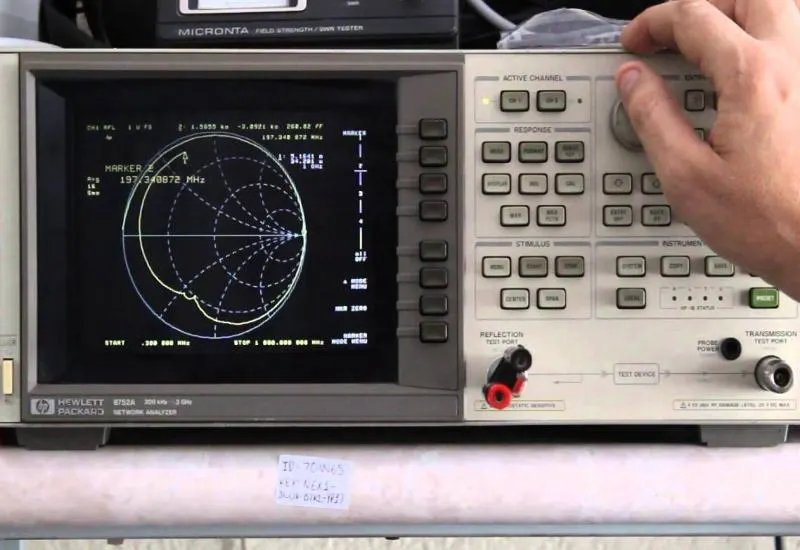
Video: reactance, inductance and farads
We review the reactances of an inductor and a capacitor on an RF vector network analyzer.
https://www.youtube.com/watch?v=DH3WYKDu8CY
Reactance
In electronics and electrical engineering, reactance is the opposition to the flow of alternating current presented by inductors (coils) and capacitors. It is measured in ohms. Together with electrical resistance it determines the total impedance of a component or circuit: reactance (X) is the imaginary part of impedance (Z).
Types of reactance
When alternating current flows through an element with reactance, energy is alternately stored and released: as a magnetic field in coils and as an electric field in capacitors. This produces a lead or a lag between the current wave and the voltage wave. That phase shift reduces the power delivered to a resistive load connected after the reactance, without consuming energy.
In a vector representation, the inductive and capacitive reactance vectors are drawn in opposite directions on the imaginary axis.
Real coils and capacitors have an associated resistance: in series with the element in coils, and in parallel in capacitors. In those cases, the total impedance (Z) is the vector sum of the resistance (R) and the reactance (X).
Inductance
Inductance depends on the physical characteristics of the conductor and on its length. If a conductor is coiled, its inductance increases: many turns give more inductance than few turns. If a ferrite core is added, the inductance increases considerably.