


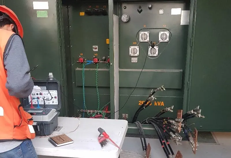
Transformer testing in Monterrey
We perform TTR turns ratio, power factor, dissipation and capacitance tests on transformers, in accordance with the IEEE C57.12.70 standard. We are members of the IEEE and of the DEIS (Dielectric and Electrical Insulation Society) #94801861.
We bring printed copies of all regulations and the national electrical code to every job. We take live video and photographic evidence of the procedures and results, so that any professional can verify them. Do not put your safety, your staff’s safety or your equipment at risk.
We use computerized touchscreen instruments for these analyses:
- Power factor, tan delta or dissipation factor of transformers. Watch our video here.
- Measurement of the turns ratio of single-phase and three-phase transformers.
- Phase deviation between the high-voltage and low-voltage windings.
- Excitation current when measuring the turns ratio.
- Measurement of the winding resistance of single-phase and three-phase transformers.
Substation analysis and testing
Maintaining the reliability of power systems requires routine checks of substations. The failure of a single piece of equipment can cause the collapse of the entire grid, with a loss of time and money. That is why maintenance programs must limit the risk of unexpected outages by identifying and preventing potential problems.
Inspection and diagnostics cover transformers, dielectric oils, circuit breakers, switchgear, panels, motors and generators, the grounding grid and protective relays, among others. Their reliability is established by testing the equipment under simulated operating conditions. Each device requires different attention, but all of them need the right test tools.
Circuit breakers
The circuit breaker is one of the most critical elements. Parameters checked include closing and opening times, synchronism, contact resistance (ductor), coil condition, pole displacement and battery condition, as well as whatever the maintenance plans call for.
We perform trip time tests on low-voltage and molded-case circuit breakers. It is also essential to verify the complete protection scheme and check the total operating time of the circuit breaker and the IEDs.
Power transformers
Maintenance includes periodic electrical tests of turns ratio, excitation current, polarization index, insulation resistance, winding resistance and short-circuit impedance, as well as analysis of cooling oils and other electrical tests.
Current and voltage transformers
Tests on protection or metering CTs/VTs usually cover turns ratio, burden, polarity, phase deviation, and excitation and insulation tests. The Raptor integrates CT and VT tests of all kinds, with high-current and high-voltage injection capability for the main primary applications in substations.
Generators and motors
Parameters analyzed include insulation resistance, polarization index, leakage current, capacitance ratio and reabsorption current.
Grounding grid
Grounding tests include different types of test and equipment depending on the objective, to verify the interaction and safe condition of the entire grid of the substation grounding system.
- Grounding: detection, by means of high current, of corroded or poor contacts in the ground circuits.
- Step and touch voltage: an automatic function for measuring the step and touch characteristics of protective grounding installations, and for uncovering dangerous elevated potentials during commissioning and maintenance.
Switchgear
Electrical switchgear integrates control, metering, protective relays, busbars, current and voltage transformers, and the corresponding circuit breaker. Maintenance must ensure the proper functioning of all these components and of their joint operation.
Panels
Testing of electrical panels (boards or switchboards) comprises inspection, quality and tests: generally wiring continuity and polarity, dielectric strength, functional tests of the protection system, relay and circuit breaker tests and other operational tests. Single-phase test sets are a practical tool for quick checks.
Protective relays
Substations have many types of protective relays, with different functions, technologies and positions. The maintenance program can range from a couple of test points on a single-phase overcurrent relay to complex end-to-end test schemes. Choosing the test equipment should take into account its adaptability to different situations and requirements, and even the competence of the personnel. Our experience over the last 23 years allows us to have a complete range of relay test equipment.
Turns ratio with a TTR
The TTR shows the number of turns of the high-voltage winding against that of the low-voltage winding. In transformers with a tap changer, the turns ratio compares the winding’s rated reference voltage with the operating voltage, or the percentage of the rated voltage to which it is referred. In these transformers the ratio must be determined for all taps and for the entire winding.
To measure with the TTR, the basic circuit in figure 1 is followed. When the detector DET is balanced, the turns ratio equals R / R1.
Acceptance criteria
The tolerance for the turns ratio, measured with the transformer unloaded, must be 0.5% on all its taps.
Opening, closing and simultaneity tests
The objective is to determine the interrupting times of power circuit breakers in their different operating modes and to verify the synchronism of their poles or phases.
- Opening time: the time measured from when the trip coil is energized until the arcing contacts separate.
- Closing time: the interval from when the closing coil is energized until the primary arcing contacts touch on all poles.
In circuit breakers with pre-insertion resistors, there is generally a difference between the closing or opening times of the primary arcing contacts and those of the auxiliary contacts in series with the resistors.
The tests listed below are considered standard, both for maintenance and for commissioning a circuit breaker:
- a) Determination of the opening time.
- b) Determination of the closing time.
- c) Determination of the close-open time in the trip-free condition (simultaneous closing and opening commands); the anti-pumping device is also verified.
- d) Determination of the synchronism between contacts of the same phase, on closing and on opening.
- e) Determination of the time difference between the main contacts and the auxiliary pre-insertion resistor contacts, on opening or closing.
- f) Determination of the delay times in the reclosing operation, if the circuit breaker is intended for that application, single-phase or three-phase.
The first three tests apply to all types of circuit breaker. Test d) applies to multi-chamber circuit breakers, e) to circuit breakers with pre-insertion resistors and f) to equipment used in reclosing. Depending on the number of chambers and the number of channels on the test set, two or more times can sometimes be determined simultaneously in a single operation.
Recommendations
- Fully isolate the circuit breaker and make sure the respective disconnect switches are in position.
- Clean the circuit breaker terminals to which the test set terminals will be connected.
Common failures of primary electrical equipment in substations
Power substations are the input and output nodes for packets of energy for transmission over long distances, regulation or distribution. Their primary electrical equipment includes power circuit breakers, instrument transformers (current, and inductive and capacitive potential), power transformers, disconnect switches and surge arresters.
Causes of failure
- Even with insulation in good condition, equipment can suffer short-duration transient overvoltages from direct or indirect atmospheric discharges (lightning). These cause insulation failures and fault or short-circuit currents many times greater than the rated current.
- Aging of the insulation can cause breakdown even at rated voltage.