


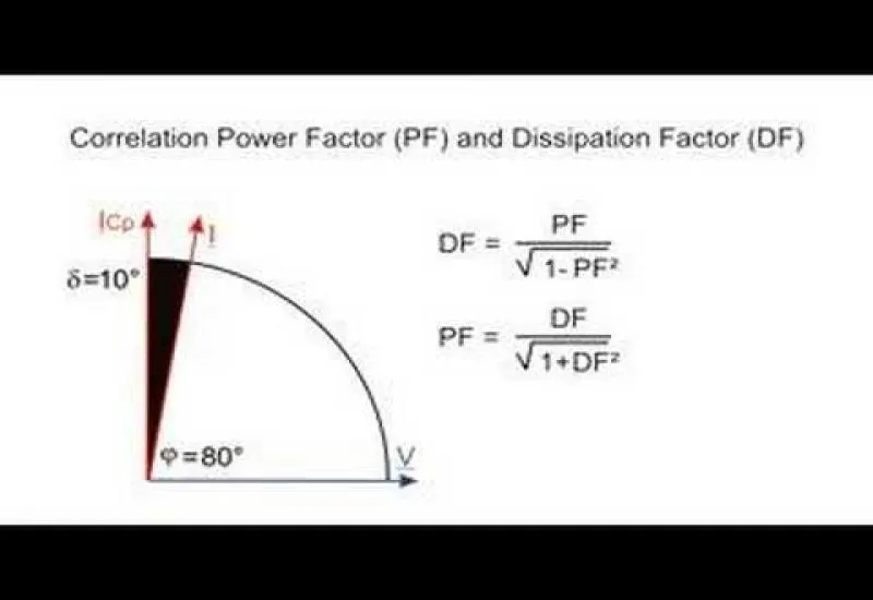
Dissipation factor testing of transformer insulation
We perform tests and rent dissipation factor or power factor equipment for transformer insulation.
Here we define the tests performed on power transformers. Two indices are the basic factors for judging insulation condition: the absorption index and the polarization index (the higher they are, the better the insulation condition). These are the tests:
a) Power factor test
It is recommended for detecting moisture and is the main criterion for judging the insulation of transformer windings.
The power factor is the ratio of the losses (milliwatts) to the load (millivolt-amperes). The value obtained depends only on the moisture and temperature of the equipment under its operating conditions, not on the thickness or area of the insulation. Because the temperature of the unit under test makes the readings vary, they must be corrected to a reference temperature of 20ºC; this is why this is an alternating current test.
Criteria for an acceptable power factor value, always referred to 20ºC: from 0.5 % in a new transformer up to 2.0 % in a contaminated transformer or one with degraded insulation. If the value exceeds 2%, the cause of the weak insulation must be investigated (for example, water penetrating the insulating oil).
b) Insulation resistance test
This is the resistance (in megohms) that an insulation offers when a direct current voltage is applied to it for a given time. It is measured by applying a constant voltage during the test. This produces a small leakage current through the insulation of the equipment under test, which falls to a constant minimum value.
Minimum insulation resistance values (at 20ºC): for 15.0 KV: 410 MEGOHMS; for 34.5 KV: 930 MEGOHMS; for 230/115 KV: 3100 MEGOHMS.
c) Turns ratio test
The transformation ratio is the turns or voltage ratio between the transformer windings (primary and secondary). The TTR is the most widely used method for this test. The TTR equipment basically consists of:
- A reference transformer with an adjustable ratio of 0 – 130
- An alternating current excitation source
- A voltmeter
- An ammeter
- A null-current detector galvanometer
- A set of terminals for connection
The test detects short circuits between turns, polarity, phase sequence, open circuits, etc.
d) Winding ohmic resistance test
This test is performed to calculate the total losses of a transformer and to identify poor contacts or points of high resistance in the windings. It can be applied to power, distribution and instrument transformers, autotransformers, voltage regulators, etc. The device used is an ohmmeter with ranges from 10 micro-ohms to 1999 ohms.
The results must be similar across the 3 phases of the windings. If they diverge, there is an internal poor contact in the phase with the highest value, which heats the equipment and eventually causes damage that forces it out of service for repair.
e) High-potential or dielectric strength test
This test shows the service condition of the insulating oil. The dielectric strength of the oil is the minimum voltage at which an arc occurs between two metal electrodes; it indicates the oil’s ability to withstand electrical stress without failing. If it is low, there is contamination with water or other contaminants. The apparatus for this test consists of:
- A transformer
- A voltage regulator (0-60 kV)
- A switch
- A voltmeter
- A test cup with two flat electrodes
The minimum permitted dielectric strength for an oil in service is 25 kV. The resistivity test is essential when investigating a transformer with abnormally low, stagnant insulation resistance, which may be caused by low oil resistivity.