


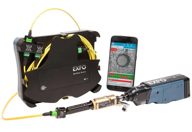
Fiber optic measurement and analysis
Fiber optic cabling is the core of today’s data communications networks. It is the predominant medium in mission-critical data center links, in backbones inside buildings and over the longest distances of campus networks. As network speeds and bandwidth demand grow, distance and loss limits tighten, and certification of fiber optic cabling becomes more important than ever.
We have equipment for rental, sale or analysis of fiber optics and their derivatives, with service throughout Mexico: optical spectrum analyzer, laser generator, OTDR equipment for optical power loss analysis, and optical power meters.
Fiber optic measurement equipment
OTDR
The optical time-domain reflectometer (OTDR) graphically plots the attenuation of an optical fiber along its entire length: distance on the X axis and attenuation on the Y axis. On that display you can determine fiber attenuation, splice losses, connector losses and the location of anomalies.
OTDR testing is the only method available to accurately locate fiber breaks in an installed optical cable whose outer jacket shows no visible anomalies. It is also used to locate losses from individual splices, connectors or any point anomaly in the installation. It shows whether a splice is within specification or must be redone.
In operation, the OTDR sends a short pulse of light down the fiber and measures the time the reflected pulses take to return. From the refractive index and the arrival time of the reflections, it calculates the distance traveled by the reflected light pulse.
OLT
OLTs (Optical Loss Testers) are a set of optical network measurement instruments consisting of a power meter and a light source. The source delivers an average power that travels through the optical fiber and loses power along the way.
The power meter shows the attenuation caused by connectors, bends, curves, splices and any other fiber defect. It gives the value of the signal loss (attenuation), measured in dBm and dB.
Fiber optic fundamentals
Optical fibers are circular dielectric waveguides that carry optical energy and information. They have a central core surrounded by a concentric cladding with a slightly lower refractive index (around 1%). They are usually made of silica with index-modifying dopants such as GeO2.
A protective coating of one or two layers of buffer material, such as acrylate, reduces crosstalk between adjacent fibers and microbending loss, which appears when fibers are pressed against rough surfaces. For further protection from the environment, fibers are normally incorporated into cables. Typical cables have a polyethylene jacket enclosing the fiber together with a strength member, such as steel or Kevlar strands.
Fiber as a dielectric waveguide
Because the core has a higher refractive index than the cladding, light is confined to the core if the angular condition for total internal reflection is met. The geometry and composition of the fiber determine the discrete set of electromagnetic fields, or fiber modes, that can propagate in it.
There are two broad classifications of modes:
- Radiation modes: carry energy out of the core, and that energy dissipates quickly.
- Guided modes: are confined to the core and propagate energy along the fiber, carrying the information and the power.
If the core is large enough, it can support many guided modes at once. Each guided mode has its own velocity and can be decomposed into orthogonal linearly polarized components. Any field distribution inside the fiber can be expressed as a combination of modes.
Mode scrambling and filtering
Many experiments with multimode fiber are sensitive to the distribution of power among the fiber modes. That distribution depends on the launch optics, fiber perturbations and fiber length.
Mode scrambling distributes the optical power among all guided modes. Mode filtering simulates the effects of kilometers of fiber by attenuating higher-order modes.
- To scramble modes, a length of graded-index fiber can be spliced between two pieces of step-index fiber. This overfills the core of the downstream fiber regardless of launch conditions.
- To filter modes, the fiber can be wound several times around a finger-sized mandrel: the bending removes the higher-order modes.
- To achieve both effects, microbending is introduced, which causes rapid coupling among all modes and attenuates the higher-order ones. One approach is to place a section of uncoated fiber in a box filled with lead shot.
Cladding mode removal
Some light is always launched into the fiber cladding. Cladding modes dissipate quickly with fiber length but can interfere with measurements. For example, the output of a single-mode fiber will not have a Gaussian distribution if light propagates through the cladding. To remove these modes, a length of the fiber coating is stripped and the bare fiber is immersed in an index-matching fluid such as glycerin.