


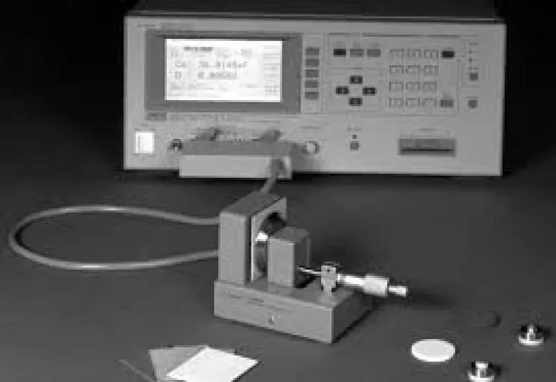
Measurements with the Keysight 4285A precision LCR
We perform measurements with the Keysight 4285A precision LCR analyzer, an accurate, reliable, high-speed instrument for measuring components and materials. For demanding RF component testing, it offers a test frequency range of 75 kHz to 30 MHz. In research and development, production, quality control or incoming inspection, the 4285A covers measurement and test requirements. We also characterize materials.
With an LCR instrument, inductive, capacitive and ohmic resistances can be determined accurately in a short time, including AC resistances and phase angles, or the quality of components. A simple GOOD/BAD comparison of values is possible with both a stationary LCR measuring bridge and portable LCR meters.
Measurement of passive components with speed and high accuracy
The 4285A LCR meter measures and evaluates passive components with high accuracy and speed. Measurements include the primary and secondary parameters for testing inductance, capacitance, resistance, quality factor and loss factor.
- Test frequencies from 75kHz to 30MHz, to analyze the passive component at different frequencies.
- Basic accuracy of 0.05%, with stable, reliable results.
- Measurement speed of 10 ms, which increases productivity with automated machines.
Scanning systems for impedance testing
Component manufacturers need higher productivity and throughput to offer lower-cost products with faster delivery and greater reliability. That is why most require impedance testing with a scanner, which improves productivity and quality control. Measuring with a scanner is different from measuring with ordinary test fixtures: measurement errors from the residual impedance of the extension cable and the scanner must be reduced. Systems with a low-frequency (LF) LCR meter and an LF impedance analyzer with a scanner are adopted, and the residual impedance problems that may appear are solved. There are real examples, such as the evaluation of temperature characteristics and the measurement of the insulation resistance of electronic components.
Review of required specifications
A scanning system lets one instrument measure many devices under test (DUTs), switching from one to another. To design it, the scanner and cable configuration are chosen, and for that the measurement requirements are clarified: accuracy, impedance of the device under test, test frequency and number of scanner channels. The required accuracy determines the maximum allowable residual impedance and stray capacitance. The measurement value and test frequency determine the cable configuration. The number of channels determines the type of scanner.
Selecting the cable configuration
The cable configuration depends on the impedance to be measured. There are two options: four-terminal pair (4TP) and shielded two-terminal (2T).
- 4TP achieves the highest accuracy over wide impedance and frequency ranges, but hardware cost increases because it requires many cables and switches per channel.
- Shielded 2T can be used if the impedance of the device under test is above 100 ohms and the measurement frequency is above 100 kHz. It allows the maximum number of channels at a lower system cost.