


What you will learn
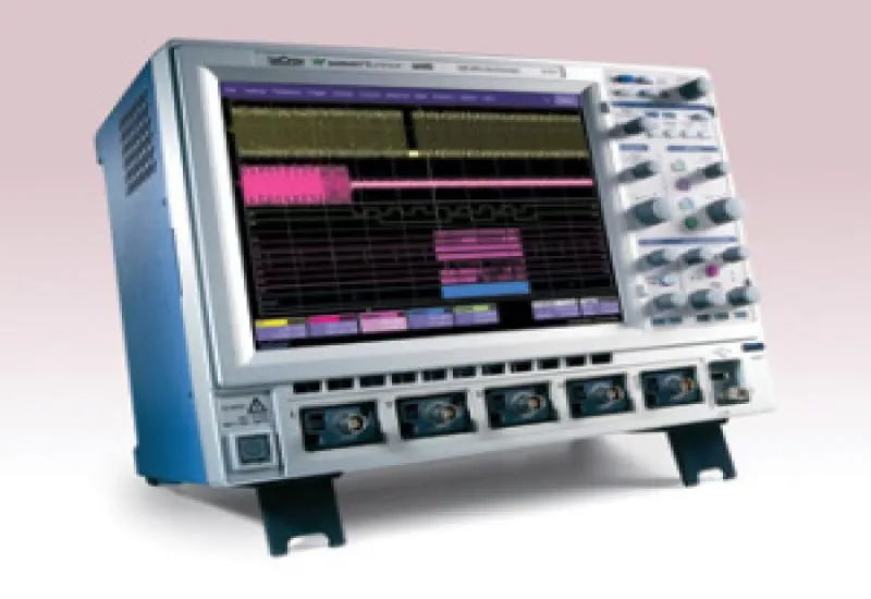
You will learn to operate the oscilloscope, whether you are a student or an engineer. We have the latest models and probes of every kind: current, active, differential and high-voltage, as well as accessories and software. We handle only professional equipment from the Tektronix, Lecroy, Agilent and Fluke brands.
- High-performance portable and benchtop equipment, with statistical functions, FFT domain and smart trigger functions.
- Safety and protection guides.
- Advanced trigger functions.
- Measurement of all kinds of signals with our special signal boards, to see the capabilities of each model.
- Learning kits for analysis equipment, with exercises and routines.
Classes are held on Saturdays, for engineers and teachers. In a few weeks you will be efficient with this equipment and will be able to adapt easily to any other, regardless of the model.
Our YouTube channel: www.youtube.com/user/electronicatutorial
What an oscilloscope is used for
Oscilloscopes are very useful in circuit analysis. They make it possible to study voltages that vary over time and, indirectly, other quantities related to voltage. For example, electric current is found by studying the voltage across the terminals of a resistor through which it flows, since it is proportional to that voltage. Other variables, such as light intensity, temperature or the pressure of a sound wave, are analyzed in a similar way.
Definition
Analog oscilloscopes
Analog oscilloscopes have a cathode-ray tube with three fundamental parts, enclosed in a glass tube with a high vacuum:
- Electron gun.
- Electron deflection device.
- Screen.
Analog oscilloscope controls
- POWER. Power switch.
- Intensity.
- Focus. Focusing control.
- XY. Feeds the channel I signal to the vertical axis and the channel II signal to the horizontal axis.
- TIME. Time base. Adjusts the time scale, or horizontal axis scale.
- X-Mag. Increases the X scale by a ratio of 10:1.
- YPos I. Vertical position of channel I.
- Ent. I. Signal input connector for channel I.
- DC/AC/GD. Selects alternating current (AC) or direct current (DC) operation on channel I. The GD position connects channel I to ground, allowing the zero to be adjusted.
- V/DIV I. Scale selector in V/div for channel I.
- Inv. I. Inverts the channel I signal.
- CH I/II. With the button out, the trigger signal acts on the channel I signal; when it is pressed in, it acts on the channel II signal.
- Dual. Displays the signals of both channels simultaneously.
- Add. Pressed: sum of channels I and II.
- Inv. II. Inverts the channel II signal.
- V/DIV II. Scale selector in V/div for channel II.
- Ent. II. Signal input connector for channel II.
- DC/AC/GD. Selects alternating current (AC) or direct current (DC) operation on channel II. The GD position connects channel II to ground, allowing the zero to be adjusted.
- YPos II. Vertical position of channel II.
Digital oscilloscopes
In addition to the sections above, digital oscilloscopes have an extra data processing system that makes it possible to store and display the signal.
When the probe of a digital oscilloscope is connected to a circuit, the vertical section adjusts the signal amplitude just as in an analog oscilloscope. The analog-to-digital converter in the acquisition system samples the signal at set time intervals and converts the continuous voltage signal into a series of digital values called samples. In the horizontal section, a clock signal determines when the A/D converter takes a sample. The speed of this clock is called the sampling rate and is measured in samples per second.
The sampled digital values are stored in a memory as signal points. The number of points used to reconstruct the signal on the screen is called the record. The trigger section determines the start and end of the signal points in the record. The display section receives these record points, already stored in memory, to present the signal on the screen.
Depending on the capabilities of the oscilloscope, additional processing can be applied to the sampled points, including a pretrigger to observe processes that occur before the trigger.
A digital oscilloscope is operated in a similar way to an analog one: to take measurements, you adjust the AMPL. control, the TIMEBASE control and the controls involved in triggering.