


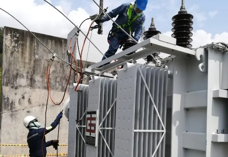
Motor and transformer testing in Monterrey
We perform ohmic resistance tests on the turns and coils of motors and transformers, using Megger equipment. Our staff are members of the IEEE and DEIS. We take the latest printed standards to the field so that all tests are carried out in accordance with current regulations.
The transformer
The transformer is probably one of the most useful electrical machines ever invented. It steps voltage and current up or down in an AC circuit. This allows electrical energy to be transmitted over long distances and distributed safely to industry and homes.
Why utilities use it
- It allows the voltage level to be set as needed.
- It is a reliable machine with no moving parts.
- It allows large amounts of energy to be transmitted from one place to another with low losses.
High voltage = low current. Low current = lower losses.
Main components (source: Siemens)
- Electrical conductors / windings
- Magnetic core
- Insulation: paper and oil
- Tap changer
- Bushings
- Cooling system
- Protection system
Maintenance testing: approach
According to the internal components of the transformer, electrical tests are divided by approach:
- Dielectric tests (insulation system): insulation resistance; capacitance and power factor; oil dielectric strength.
- Electrical tests (mechanical system): winding ohmic resistance; turns ratio, polarity and phase; excitation current.
Test standard: IEEE C57.152, guide for field testing.
Megger insulation resistance
Insulation resistance is the opposition an insulating material offers to the flow of current when a potential difference is applied to it. The current resulting from applying a voltage to an insulating material is called leakage current. This test is performed with DC.
The test is known as Megger, megado or megging, and is carried out in accordance with the standards IEEE Std P43-2000, ASTM F855, ASTM D257 and ASTM D1711.
- For motors it is typically performed at 500 – 1000 V, depending on the device under test and its operating voltage.
- Factors affecting the test: contamination of the insulation, humidity and temperature.
- The test is done in the time domain: at 1 minute the dielectric absorption ratio (DAR) is obtained, and at 10 minutes the polarization index (PI). The measured values are used to plot the behavior of the insulation.
Turns ratio (TTR)
The turns ratio is the ratio between the number of turns of the primary winding and that of the secondary. It is known as TTR, is performed with AC and follows the IEEE C57 test standard.
This test detects:
- Manufacturing defects in the windings.
- Incorrect polarity.
- Short circuit between turns.
- Winding-to-ground fault (grounded phase).
- High-resistance connections.
- Defective tap changer.
The measured ratio must be within 0.50% of the nameplate value, as the maximum acceptable error.
All TTR measurements assume that the voltage ratio of a transformer at no load is equal to the ratio between the numbers of turns:
TTR = NP / Ns = VP / Vs
Where NP is the number of primary turns, Ns the number of secondary turns, VP the primary voltage and Vs the secondary voltage.
Single-phase transformer
- Test standard: ANSI.
- Connection diagram: No. 1.
- Test leads H0, H3, X0 and X3 must remain disconnected and isolated from the transformer.
Autotransformer with tertiary
- Test standard: ANSI.
- Connection diagram: No. 1.
- Test leads H0, H3, X0 and X3 must remain disconnected and isolated from the transformer.
How do you test an electric motor?
Three-phase motors
- Inspect the appearance of the motor: damage to the frame, the cooling fan blade or the shaft.
- Turn the shaft by hand to check the condition of the bearing. It must turn freely, with no friction in the bearings.
- Write down the motor nameplate data.
- Ground continuity: with an ohmmeter, verify that the resistance between ground and frame is less than 0.5 Ω.
- Power supply: correct voltage of 230 volts per line, and 415 V between L1 and L2, L2 and L3, and L3 and L1 (three-phase).
- Make sure the power terminal is in good condition. Check the connection of the bar to the terminal (U, V, W) and the connection type: delta or star.
- Confirm the supply voltage for the electric motor: 230/400.
- With the multimeter, verify coil continuity from phase to phase (U to V, V to W, W to U). Each pair must show continuity if the coil is good.
- Check the resistance of each coil with a multimeter or ohmmeter. The readings must be equal or nearly equal.
- Coil insulation resistance: with the insulation tester on the 500 volt scale (DC 1000 V), check from phase to phase and from phase to ground (E). The minimum test value for the electric motor is 1 MΩ.
- With the motor running, measure the current with a clamp meter and compare it with the FLA on the nameplate.
- With all steps complete, decide whether the motor is good or needs repair.
Single-phase motors
Check the motor coil with a multimeter or ohmmeter (C to S, C to R, S to R). The start-to-run reading must equal C to S + C to R.
A sealed compressor motor has 3 terminals: Common (C), Start (S) and Run (R). To identify them:
- The highest resistance is between the Start and Run terminals.
- The medium resistance is between Start and Common.
- The lowest resistance is between Run and Common.
Use the winding insulation tester on the 500 volt scale and check the windings against ground (C to E, S to E, R to E). With the motor on, measure the amps with a clamp meter and compare them with the FLA on the nameplate. On that basis, decide whether the motor is good or needs repair.