


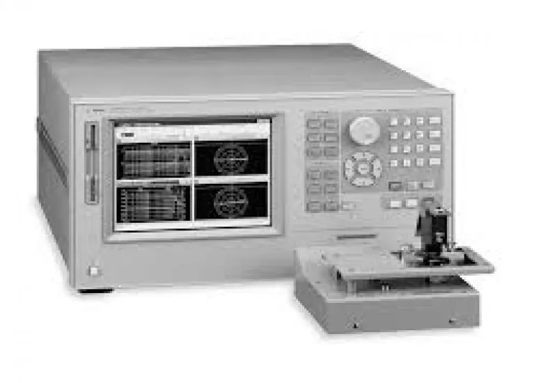
Agilent 4291B RF Impedance / Material Analyzer
The Agilent 4291B RF Impedance/Material Analyzer is designed to measure surface-mount electronic components, dielectric and magnetic materials and RF components simply and with high accuracy.
It measures impedance over a wide spectrum of operating frequencies, from 1MHz to 1.8 GHz. It can be used to test:
- Chip capacitors, chip inductors, coils, varicap diodes and other passive components.
- Integrated circuit packages and packaging materials.
- Printed circuit boards (PCB).
- Dielectric and magnetic materials.
Its features usually interest component manufacturers, RF and digital equipment designers and researchers:
- Wide frequency range, from 1MHz to 1.8GHz, for testing RF components and materials.
- Measurement accuracy and repeatability from 0.1 Ohm to 50 KOhms.
- 4 SMD test fixtures for different sizes of chip capacitors and inductors (size: 0.5 mm to 20 mm).
- Dielectric test fixture and internal function for measuring permittivity, including Cole-Cole Plot and relaxation time.
- Magnetic test fixture and internal function for measuring permeability.
- Direct measurement of material and impedance parameters versus frequency, time, humidity or temperature.
- Impedance accuracy of +/- 0.8 %.
- Advanced calibration and error compensation.
- Independent parameter selection on two channels.
- Two test fixtures with an operating temperature from minus 55 degrees Celsius to plus 200 degrees Celsius.
Summary and features
The equipment consists of:
- A mainframe computer unit.
- A test station with a 1.8 m cable.
- Test heads.
- SMD test fixtures.
- A keyboard.
- A calibration kit.
- A high-temperature test head.
Main specifications
- Low-error 1.8 m cable connecting the analyzer to the test station. It allows analysis away from the analyzer without losing accuracy.
- Direct voltage/current measurement technique.
- High Q accuracy, which makes it possible to analyze low-loss components.
- Internal synthesizer that sweeps frequencies from 1 MHz to 1.8 GHz with a resolution of 1 MHz.
- Advanced calibration function and error compensation.
Description
The Keysight 4291B RF impedance/material analyzer measures surface-mount components and dielectric or magnetic materials easily and with high accuracy. It uses a direct voltage measurement technique, rather than the reflection technique, to measure impedance more accurately over a wide impedance range.
Basic impedance accuracy is +/- 0.8%. High Q accuracy makes it possible to analyze low loss components. An internal synthesizer sweeps frequencies from 1 MHz to 1.8 GHz with a resolution of 1 MHz. A low-error 1.8 m connecting cable joins the analyzer to a test station and allows measurement away from the analyzer without losing accuracy. Advanced calibration and error compensation eliminate measurement error factors and ensure high accuracy and repeatability on DUT/MUT.
The Keysight 4291B offers automatic level control and test signal monitoring through the IBASIC programming function; devices can be measured at constant voltage or current. Measurement errors depend on the impedance characteristics, with optional DC bias (above 40 V and 100 mA). With one button, the built-in equivalent circuit analysis function calculates the values of five circuit types.
It has two measurement channels; on each one you can select a single impedance parameter (for example Z) or a dual one (for example Z-Theta). The split-screen color TFT monitor can show the two active traces and memory traces (stored in RAM). A built-in floppy disk drive handles stored programs and test data in LIF or MS-DOS format. With native IBASIC, external accessories such as a temperature chamber or a wafer prober can be controlled directly from the Keysight 4291B. No separate controller is required.
Material evaluation
The Keysight 4291B makes device evaluation simple and sophisticated, and improves the quality and efficiency of that evaluation. It offers everything needed to measure dielectric and magnetic materials over an extensive range (1 MHz to 1 GHz).
Specification conditions
- Specifications indicate the guaranteed performance of the equipment over a temperature range of 0 C to 40C.
- Supplemental characteristics give useful information with non-guaranteed parameters, noted as typical, nominal or approximate.
- Warm-up time is equal to or greater than 30 minutes after power-on, for all specifications.
- Stimulus and measurement accuracy specifications are defined at the APC-7 type connector located on the test head connected to the instrument.
Stimulus ranges
- Voltage range: 1 MHz < frequency < 1GHz (open terminals): 0.2 mVrms to 1 Vrms.
- Current range: 1 MHz < frequency < 1GHz (shorted terminals): 4 Arms to 20 microArms.
- Power range: 1 MHz < frequency < 1GHz (terminals with 50 Ohms resistance): -67 dBm to 7dBm.
Options and accessories
- 16092A: spring clip fixture. Designed to evaluate the impedance of leaded and SMD components.
- 16190B: test equipment for verifying the accuracy of impedance measurements of LCR meters or impedance analyzers with a 7 mm measurement terminal.
- 16192A: SMD test fixture with parallel electrodes. Designed to measure the impedance of side electrodes on SMD components.
- 16194A: high-temperature component test fixture. Designed to measure axial and radial leaded devices.
- 16196A: SMD test fixture with parallel electrodes, DC to 3 GHz. Its coaxial structure allows RF impedance measurements up to 3 GHz.
- 16196B: SMD test fixture with parallel electrodes, DC to 3 GHz. Its coaxial structure allows RF impedance measurements up to 3 GHz.
- 16196C: SMD test fixture with parallel electrodes, DC to 3 GHz. Its coaxial structure allows RF impedance measurements up to 3 GHz.
- 16196D: SMD test fixture with parallel electrodes, DC to 3 GHz. Its coaxial structure allows RF impedance measurements up to 3 GHz.
- 16197A: deep-electrode SMD test fixture. Designed to evaluate the impedance of deep SMD electrodes.
- 16200B: external DC bias adapter. Supplies bias current of up to 5 amperes DC through a 7mm port, from an external DC source.
- 16453A: dielectric test fixture. Designed to accurately measure dielectric constants and loss tangent on the E4991A/4291A/B.
- 16454A: magnetic material test fixture. Designed to accurately measure the permeability of toroid-shaped magnetic materials.