


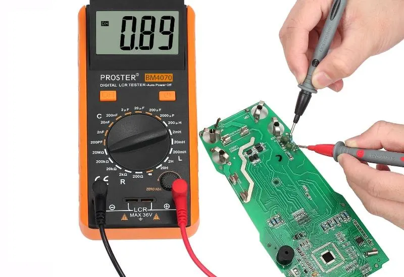
Video: basic measurements with an LCR multimeter
Brief video tutorial on using an LCR meter. We explain its basic functions.
What a multimeter is
A multimeter, also called a polymeter, tester or multitester, is a portable electrical instrument. It directly measures active electrical quantities, such as currents and potentials (voltages), or passive ones, such as resistances and capacitances. Measurements can be made on direct or alternating current and over several measurement ranges. There are analog and digital versions; the function is the same, with some added variations.
Ammeter
To make the multimeter work as an ammeter, a resistor is connected in parallel with the measuring instrument. Its value depends on the amperes to be reached when the needle arrives at full scale. The multimeter has as many switchable resistors as it has different full-scale ranges. For example, for scales of 10 milliamperes, 100 milliamperes and 1 ampere there will be three switchable resistors.
To measure high currents, separate input terminals are usually provided. The internal circuits are built with wire and components suitable for withstanding that current.
Voltmeter
To make the multimeter work as a voltmeter, a resistor is connected in series with the measuring instrument. Its value depends on the volts to be reached when the needle arrives at full scale. Here too there are as many switchable resistors as full-scale ranges. For example, for 10 volts, 20 volts, 50 volts and 200 volts there will be four different resistors.
Ohmmeter
The ohmmeter measures resistances. An internal battery drives a current through the resistance to be measured, the instrument and an additional adjustment resistor.
When the measuring terminals are short-circuited, maximum current flows through the galvanometer. That value is associated with R = 0. The adjustment resistor is used to trim the current until it matches full scale, and that division is marked 0 ohms. Connecting the resistance to be measured across the terminals causes a voltage drop, and the needle moves toward lower current values, that is, to the left. That is why the resistance scale increases from right to left.