


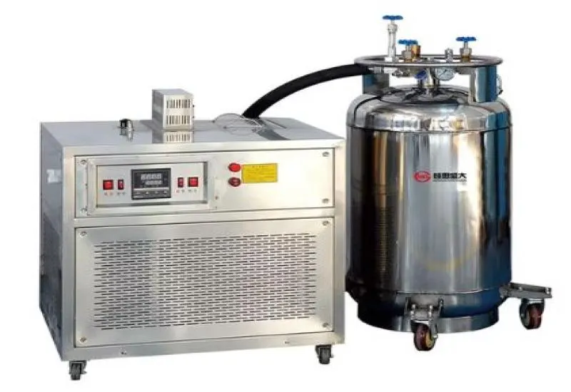
Thermal shock testing
We perform thermal shock testing to identify bonding failures, delamination, package cracking, solder joint fracture and coating problems in electronic components. We apply shock cycles with rapid exposure between hot and cold chambers, or with controlled use of liquid nitrogen, to achieve very fast temperature drops and rises while keeping the profile reproducible.
Equipment and configuration
- Sun EC01 chamber (Rev. B) with doors and a pass-through for sample transfer.
- Liquid nitrogen injection and control system with vaporizer and controlled-flow valves, to accelerate cooling.
- Integrated ETS 514 controller for sequences and logging.
- Contact and surface sensors on the samples to verify stabilization times.
- Optional: chamber bank for transfer between high and low temperature, if a dual-chamber method is required.
Test types
- Thermal shock by chamber immersion (rapid transfer between zones).
- Fast-ramp shock using cryogenic flow (nitrogen) to reach -60 °C to -80 °C, depending on safety and vapor density.
- Repeated shock cycles to evaluate thermal fatigue and mechanical-electrical behavior.
Methodology
- Define criteria: temperature limits, number of cycles, required rate of change (°C/min) and electrical measurement points.
- Preparation: suitable mechanical fixturing to prevent movement that damages contacts and cables; definition of sealed ports for signal routing.
- Controlled execution: apply the thermal shock with continuous logging. Functional monitoring can be performed during transitions (power on/off tests, S-parameter measurements, continuity, noise).
- Post-test evaluation: visual inspection, electrical measurements before and after, solder tests and microscopy if applicable.
Liquid nitrogen precautions and safety
- Operation by personnel trained in cryogenics.
- Use of PPE: cryogenic gloves, face shield, safety glasses and suitable clothing.
- Room ventilation and oxygen detection, to avoid oxygen displacement hazards.
- Procedures for handling Dewar vessels and injection systems; preventive maintenance of the vaporization system.
- Electrical hazards when combining cryogenics and energized equipment: design safe cable routes and suitable insulation.
Standards and references
- IEC 60068-2-14 for thermal shock.
- MIL-STD-810: combined thermal shock and vibration methodologies.
- OSHA safety recommendations and local standards for handling cryogens.
Deliverables
- Per-cycle log with times and temperatures (CSV + graphs).
- Results of the electrical tests performed in situ.
- Inspection report and design or corrective recommendations.
Metrological temperature control
In our environmental analyses and laboratory tests where temperature is a critical parameter, we verify our thermal systems in-house. Each test is backed by temperature validation in our dry-well calibrator:
- Operating range from -30 °C to 150 °C.
- Resolution of 0.01 °C.
- Thermal stability of ±0.02 °C.
- Display accuracy of ±0.1 °C.
- Block uniformity (horizontal ≤ ±0.05 °C) and controlled vertical gradient.
This confirms the stability, uniformity and accuracy of the test conditions, with traceable results. The expanded uncertainty of the system is determined according to the operating point, the sensor under test and the process conditions.