


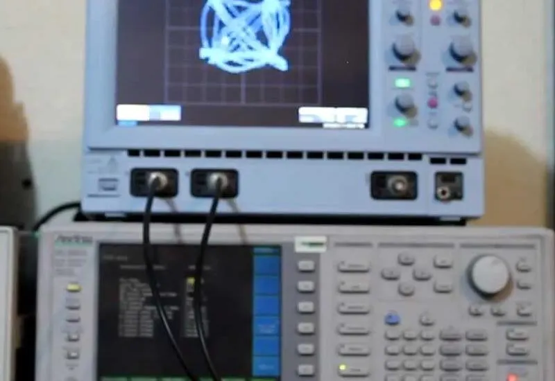
4QAM or QPSK digital modulation on the oscilloscope
We generate and view 4 QAM vector and constellation diagrams on an oscilloscope, as an introduction to the basics of digital modulation.
What an oscilloscope is
An oscilloscope is an electronic measuring instrument for the graphical representation of electrical signals that can vary over time. It is widely used in signal electronics, often together with a spectrum analyzer.
It presents the values of electrical signals as coordinates on a screen: normally the X axis (horizontal) represents time and the Y axis (vertical) represents voltage. The resulting image is called an oscillogram.
Use
An oscilloscope basically has two types of controls, which adjust the input signal and allow it to be measured on the screen. This makes it possible to see the shape of the signal to be measured.
Digital modulation
Modulation covers the set of techniques used to carry information on a carrier wave, typically a sine wave. These techniques make better use of the communication channel, which allows more information to be transmitted simultaneously and improves resistance to noise and interference.
According to the American National Standard for Telecommunications, modulation is the process, or the result of the process, of varying a characteristic of a carrier in accordance with an information-bearing signal.