


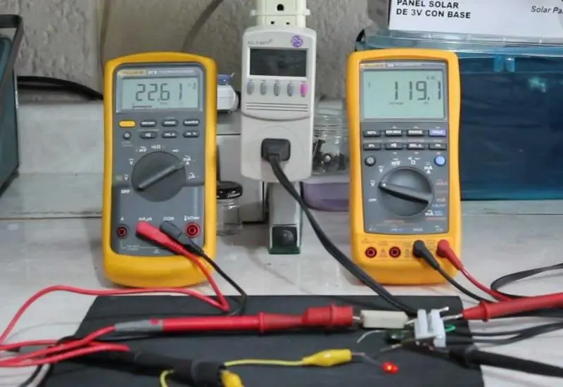
About the video
It explains what power factor (PF), impedance and reactance are. It includes an experiment that shows the differences between real power and apparent power.
Power factor
The power factor (p.f.) of an alternating current circuit is the ratio of active power (P) to apparent power (S). It measures the ability of a load to absorb active power. That is why p.f. = 1 in purely resistive loads, and p.f. = 0 in ideal inductive and capacitive elements without resistance.
The power factor of a piece of equipment depends on the lag or lead it causes in the circuit current (I) relative to the voltage (V).
Reactance
It is the opposition to the flow of alternating current presented by inductors (coils) and capacitors. It is measured in ohms and its symbol is Ω. Together with electrical resistance it determines the total impedance (Z) of a component or circuit: reactance (X) is the imaginary part of the impedance and resistance (R) is the real part.
Types of power
In an alternating current circuit there are three types of electrical power:
- Active power (P), resistive
- Reactive power (Q), inductive
- Apparent power (S), total
Active or resistive power (P)
When a resistor (R) or resistive load is connected to an alternating current circuit, the useful work of that load determines the active power the source (EMF) must supply. It is represented by the letter P and its unit is the watt (W).
The most commonly used multiples of the watt are the kilowatt (kW) and the megawatt (MW). The submultiples are the milliwatt (mW) and the microwatt (µW).