


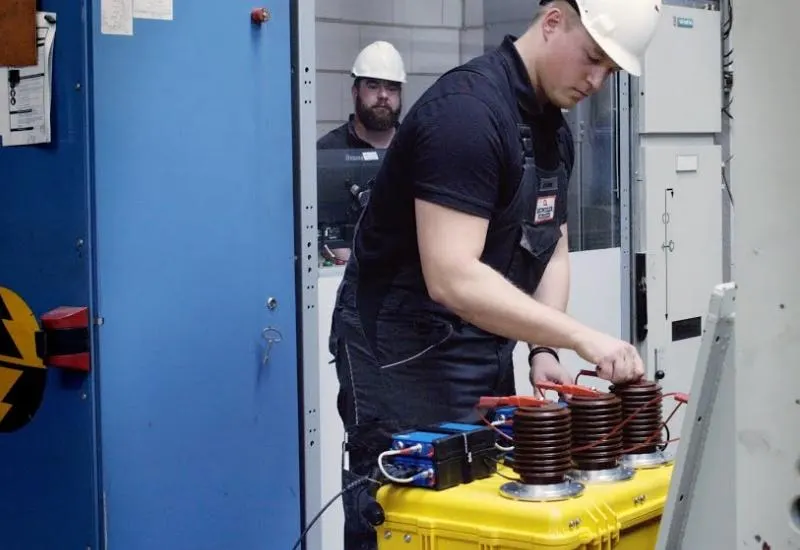
Non-intrusive partial discharge (PD) analysis
What a partial discharge is
It is a localized electrical discharge in an insulating element that does not completely bridge the gap between two conductors at different potentials. It can occur in medium- and high-voltage equipment. In electrical engineering, partial discharge (PD) is a localized dielectric breakdown in a small region of solid or liquid insulation subjected to high voltage stress. PD activity, once detected, will always increase.
Where they occur
They occur because of a high, non-uniform electric field. They are typically found in the insulation of high-voltage lines, transformers, turbines, busbars inside enclosures, surge arresters, switchgear, high-voltage coils, circuit breakers and capacitors. They are common in power generation facilities, transmission networks and distribution networks.
Our service
We analyze partial discharges in all types of insulation: alternators, generators, motors, transformers, cables and others. We also rent partial discharge equipment with a technician. Our laboratory is in Monterrey, Nuevo León, Mexico, and we can travel to other states of the Republic.
The partial discharge test
Dielectric diagnostic methods provide evidence of changes in the condition of the insulation and are key to the quality, safety and reliability of power transformers. They include dielectric response measurement, frequency response analysis, insulation resistance, capacitance, dissipation factor and partial discharges, among others.
Why measuring PD matters
A PD-type discharge can damage the surrounding insulation by erosion. The corrosive gases it emits also damage the insulation and metal parts, and create additional areas subject to discharges. Eventually the insulating medium can fail and produce flame, damage to apparatus, supply interruptions, fires and explosions.
PD can damage the insulation of the bushings and windings of power transformers long before the insulation fails, and cause costly outages. That is why it is important to recognize the source of PD, find it and eliminate it when necessary. The PD measurement system gives test engineers highly sensitive information for detecting even the smallest weak points in the insulation.
Measurement on power transformers
There are several tests on the insulation of the coils and bushings of a transformer to measure PD, and one test to locate the origin of PD in the coil insulation.
The specific tests and configurations are determined by the type of transformer and by the standard to which the measurement is made. Depending on the type of bushing, the analysis system is connected to the capacitive tap of the bushings or to an external coupling capacitor, which allows electrical PD to be measured on the transformer. PD is measured in V (according to IEEE standards) or in pC (according to IEC 60270). In environments with heavy interference, advanced noise suppression techniques are usually applied to minimize irrelevant data.
PD can also be measured inside the tank of liquid-insulated transformers with ultra-high frequency (UHF) sensors. UHF measurement serves to verify the results: PD pulses from an electrical measurement at the bushings are accepted only if there is also a UHF pulse coming from the tank. For continuous risk management, an online dielectric condition monitoring system can be installed to continuously evaluate the insulation of the bushings and transformers.
Acoustic defect location
Once PD activity is detected, acoustic measurements allow defects to be located precisely. They are carried out after PD is detected in factory acceptance tests and are part of on-site diagnostics during the service life of power transformers. With the exact location known, corrective measures can be planned and carried out efficiently to prevent failure.
Several acoustic sensors are mounted magnetically on the surface of the tank. Each sensor measures the propagation time of the acoustic signal from the PD source to the tank wall. The defect location is calculated from the time differences, the sensor positions and the propagation speed, comparing the data from all the sensors simultaneously. IEEE C57.127-2007 describes the typical workflow for an acoustic measurement.