


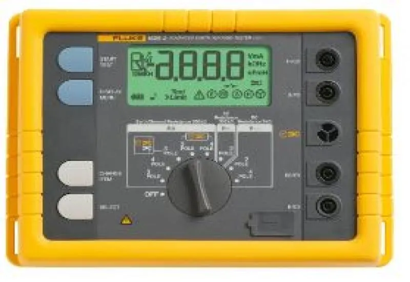
Grounding and lightning rod measurements and tests
We rent ground resistance testers and measure grounding in Monterrey. We have testers and carry out grounding and lightning rod tests and studies in accordance with NFPA 780. We measure resistance with 3 stakes according to the Mexican standard NOM-022-STPS-2015 and verify with Megger ground clamps.
We bring printed copies of the standards and the national electrical code to every job. We take video and live photographic evidence of the procedures and results, so that any professional can verify them. You can also take video of our work. Do not put your safety, that of your personnel or that of your equipment at risk.
Other field services
- Soil resistivity per meter, for ground electrodes and for cathodic protection of gas or liquid pipelines.
- 4-stake Wenner method ASTM G57.
- Oil tests in the field, in front of the customer.
- Megger-type insulation tests and general analysis of substation transformers.
We are based in Monterrey and travel throughout Mexico. All work follows current regulations. Our professional staff are members of the IEEE (Institute of Electrical and Electronics Engineers) and of the IEEE Dielectrics and Electrical Insulation Society (DEIS) #94801861. This gives access to current standards, professional forums and research material.
YouTube channel: www.youtube.com/user/electronicatutorial
Equipment and measurement modes
We have professional Fluke and Megger equipment, with or without stakes, in different models and prices to fit your budget. You can rent ground resistance testers in the Monterrey area, or we travel throughout Mexico.
- Two-, three- or four-pole tests, or clamp tests without stakes.
- Measurement at 4 different frequencies to suppress interference.
- In areas of very strong interference, such as near high-voltage lines, the equipment averages over a long period to determine a stable resistance value.
- Soil resistivity to decide where to install lightning rods.
- Studies measuring electrodes at different depths to obtain real results.
Reference values and how to lower resistance
NFPA and IEEE establish that the optimum resistance should be 5 ohms or less. Resistivity changes with electrolytes, soil type, moisture and ambient temperature. The goal of the test is to find the place with the lowest resistance that also makes economic and physical sense.
The NEC code (1987, 250-83-3) requires an electrode to have a minimum length of 2.5 meters. The length and depth of the electrode or rod, its diameter, the number of electrodes installed and the design of the grounding system also have an influence.
Greater depth
As a rule, doubling the depth of the electrode reduces resistance by 40%.
Larger diameter
Where it is not possible or practical to go deeper, the rod diameter can be increased, but the difference is small: doubling the diameter lowers resistance by only 10%.
Parallel electrodes
Adding more electrodes in parallel lowers resistance if the spacing between them is at least equal to their depth. This way the resistance spheres do not interfere with each other. This technique is less exact, because each ground zone has different resistances.
Complex system
The ultimate option is to design a system with multiple electrodes, a grid mesh, ground plates and ground loops.
Loop resistance measurement
This applies to commercial and industrial installations and utility networks. Clamp testing simplifies ground loop measurement and allows leakage currents to be measured non-intrusively. It checks the ground loop and continuity without opening the circuit.
Stakeless measurement system
The stakeless method eliminates the need to disconnect parallel systems and to look for places for auxiliary stakes. The resistance clamp goes around any point of the ground circuit or the connecting cable. One half of the clamp induces a set voltage and the other half measures the current. The meter automatically determines the loop resistance.
Importance of grounding
Any instrument connected to an electrical supply is exposed to electrostatic discharges, electromagnetic interference, lightning and human error. These events put the integrity of people and property at risk.
Physical ground is an actual connection to the earth. Grounding is the direct electrical bonding of a part of the circuit, or of non-conductive parts external to it, to a ground connection through electrical conductors. Many instrumentation errors, harmonic distortion and power factor problems are due to an ineffective grounding system.
Over time and with changes in weather, soil resistivity and the condition of the rods and connections change and alter the resistivity of the connection. There are several methods for verifying it in different types of systems. One cause of electrocution and electrical accidents in industrial environments is equipment that is poorly grounded or lacks an effective ground.
NOM 001 details recommendations for sizing cables and specific connections. The responsibility does not end there: paths and common points must be created that eliminate potential differences and electrical noise, and that give a fault a good return path to the source so that the protective devices clear it without affecting the equipment.
IEEE 80 points out that the foundation of good power quality is a grounding system that is efficient and suited to the needs of industry and electronic equipment.
The electrical grounding study has a direct impact on electrical safety. An effective system physically protects plant personnel and prevents atmospheric effects from damaging facilities and equipment. NOM-001-SEDE-2012, art. 250, states that systems and circuits must be grounded to limit overvoltages from lightning, transients or accidental contact with higher-voltage lines, to stabilize the voltage to ground during normal operation, and to facilitate the action of overcurrent devices during ground faults. In addition, the system must meet these requirements in order to obtain and maintain ISO 14000 certification.
Why determine soil resistivity
It is necessary to design the ground connection of new installations (open-field applications) and to achieve the required resistance.
Composition, moisture and temperature influence resistivity. Soil is rarely homogeneous, and its resistivity varies geographically and with depth. Poor soil conditions can be overcome with more sophisticated connection systems.
Moisture content changes with the season, the nature of the sublayers and the depth of the water table. Since soil and water are more stable in deep strata, we recommend placing the rods as deep as possible, in the water table if feasible, and in a place with a stable temperature.
To be effective, a connection system must be designed to withstand the worst possible conditions.
How soil resistivity is calculated
The measurement procedure is the Wenner method, universally accepted and developed by Dr. Frank Wenner of the U.S. standards agency in 1915 (F. Wenner, A Method of Measuring Earth Resistivity; Bull, National Bureau of Standards, Bull 12(4) 258, p. 478-496; 1915/16).